


Buck and Boost Converters: How They Work and Where They’re Used

Modern electronic systems need efficient voltage regulation as devices become smaller and power demands rise. Buck and boost converters step DC voltage down or up while supporting efficiency, thermal control, and reliable operation.
How a Buck Converter Steps Voltage Down

Principle of Operation
A Buck converter serves as a step-down DC-DC converter, adept at transforming a higher input voltage to a lower, regulated output voltage (Vout). The core components include an inductor, a diode, a switch (commonly a MOSFET), and a capacitor. By modulating the pulse-width modulation (PWM) duty cycle of the MOSFET, the Buck converter fine-tunes the Vout.
Advantages
- High Efficiency: Buck converters excel in recycling excess voltage through the inductor, achieving efficiencies often above 90%.
- Minimal Heat Dissipation: The high-efficiency operation of the Buck converter inherently curtails heat generation, mitigating the need for heat sinks or other cooling systems.
- Broad Input Voltage Spectrum: These converters can handle a wide array of input voltages, making them versatile in diverse applications like solar power systems and automotive electronics.
- Swift Transient Response: The Buck converter's rapid transient response to changes in load or input is a crucial asset in real-time applications.
How a Boost Converter Steps Voltage Up
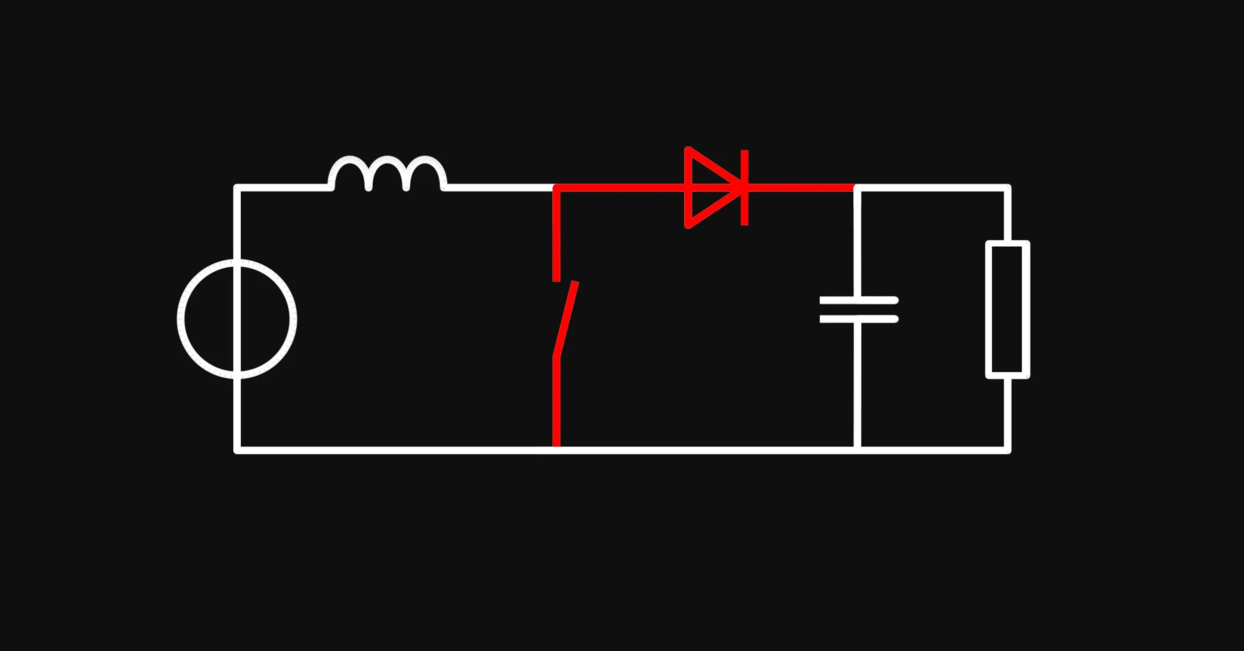
Principle of Operation
In contrast to the Buck converter, a Boost converter acts as a step-up DC-DC converter. It elevates a lower input voltage to a higher Vout. The essential components—inductor, diode, MOSFET, and capacitor—are arranged differently to achieve this function.
Advantages
- Voltage Amplification: Boost converters can significantly elevate the input voltage, making them invaluable in low-voltage applications like photovoltaic systems.
- Compact Footprint: The inductor-centric design of the Boost converter allows for a more compact form factor compared to transformer-based solutions.
- High Efficiency: Similar to Buck converters, Boost converters also maintain high efficiency, particularly when the voltage differential is minimal.
- Inrush Current Limitation: The inductor inherently restricts inrush current, adding an extra layer of system protection.
Buck-Boost and SEPIC Converters for Variable Input Voltage
Buck-boost and SEPIC topologies can regulate an input that moves above or below the target output, making them useful for batteries and other variable sources.
Special Mention: Flyback and Inverting Converters
Flyback converters are useful for applications requiring isolated outputs, while inverting converters can invert the polarity of the output voltage, expanding the range of potential applications.
Buck and Boost Converter Applications
- IoT Devices: The Internet of Things (IoT) is burgeoning, and with it comes the need for low-power, high-efficiency devices—perfect candidates for Buck and Boost converters.
- Electric Vehicles (EVs): EVs, with their varying voltage levels and subsystems, stand to gain significantly from these power converters.
- Renewable Energy Systems: In solar and wind energy setups, where voltage can fluctuate, these converters ensure a stable output for either storage or immediate use.
- Portable Electronics: Battery-operated devices like smartphones and laptops benefit from efficient power management, a role well-suited for these converters.
Conclusion
Buck and Boost converters, as specialized DC-DC converters, have become irreplaceable in the realm of modern electronics. Using simple components and concepts, like inductors, capacitors, MOSFETs, and PWM control, Buck and Boost converters work miracles for power circuits. Their unique advantages in terms of efficiency, versatility, and compactness make them indispensable in shaping the future of power management solutions.
More in PCB Design & Engineering Fundamentals

What Is a PCB? A Beginner's Guide to Printed Circuit Board Design

What is Schematic Design? All You Need to Know

PCB Stackup Design: How to Build the Right Layer Structure

Best PCB Routing Techniques for Clean Circuit Board Layouts

How to Read PCB Schematics: A Beginner-Friendly Guide

PCB Schematic Best Practices for Clean Circuit Design

Schematic Capture Explained: How Engineers Create Circuit Diagrams

What Is EDA Software? A 2026 Guide to Tools and Companies

Best Schematic Capture Software in 2026: 7 Tools Compared

Common Schematic Design Mistakes and How to Avoid Them

PCB Netlists Explained: How Schematics Connect to Layouts

What Is a Netlist? Understanding the Basics of Electronic Design Automation

PCB Symbol Design: Best Practices for Clean Schematics

Making Parts Just Got Easier: Introducing Parametric Symbols

Create Satisfying Schematics with these Updates

Electronic Circuit Design Explained: From Schematics to PCB Layout

Designing PCBs: What Are the Essential Steps

Hardware Design Workflow: From Schematic Capture to Manufacturing

What Is a Functional Block Diagram and Why Is It Critical in System Design

PCB Design Basics: What You Need to Know Before You Start

Diode Symbols: How to Identify Common Diodes

Ultra Librarian joins Flux to Take the Hard out of Hardware

Flux Now Has the World's Largest eCAD Part Library

Capacitor Symbols Explained: Types, Polarity, and Schematic Use

MOSFET and Transistor Symbols Explained: NMOS, PMOS, NPN, and PNP

How to Convert PDF Schematics into Editable EDA Files Using AI

Resistor Symbols Explained: Fixed, Variable, Thermistor, and Photoresistor Symbols

Fuse Symbols Explained: Electrical, Thermal, and Circuit Protection Symbols

How to Learn PCB Design: A Step-by-Step Roadmap for Beginners

Crosstalk, Reflections, and the Real Challenges of Signal Integrity

What Is Signal Integrity in PCB Design? A Practical Guide

High-Speed PCB Design: Layout Rules, Signal Integrity, and Routing Best Practices

EMI/EMC in PCB Design: How to Reduce Interference

PCB EMI Problems: Causes and Solutions

Differential Pair Routing Guidelines and Controlled Impedance Best Practices

PCB Impedance Control: A Practical Guide for Engineers

Introducing Curved Traces in Flux

Analog vs Digital PCB Design: Key Differences Explained

Pi Filters Explained: Design, Components & Applications

RS485 Explained: Wiring, Specifications, and Applications

What is RS232?

SPI vs. I2C: Which Communication Protocol Should You Use?

RJ45 Connectors: Pinouts, Categories, Uses, and Testing

CO2 Sensor Technology: How These Devices Detect Carbon Dioxide

Hall Effect Joysticks: How They Work, Benefits, and Uses

What Is an Oscillator? Beginner's Guide to Oscillating Circuits

Flexible PCB Design Guide: Materials, Layout, and Applications

Rigid-Flex PCB Design: Benefits, Challenges, and Layout Tips
The RF Engineer's Guide to Designing Printed Trace Antennas

SMA Connectors Explained: Types, Applications, and PCB Design Considerations

RC Low-Pass Filter: Formula, Cutoff Frequency & Design

NFC vs RFID: Board Design, Tags, and Reader Choices

Low-Pass vs High-Pass Filter: Differences and Examples

How to Choose a Bluetooth Module for Your PCB Design

Decoding Voltage Regulators: How They Work in Everyday Electronics

Voltage Regulators: How They Work, Types, and Applications

Buck Converter Design: Components, PCB Layout, and Formulas

LM2596 in Action: Case Study of Its Application in Power Supply Units

Guide to GND Fills and Power Planes

Power Distribution Network (PDN) Design in PCBs

PCB Grounding Techniques for Noise Reduction and Stability

Designing High-Current PCBs: Layout and Safety Considerations

How to Calculate PCB Trace Resistance

Voltage Drop Calculations: Formulas, Factors, and Guidelines

AC to DC Converter: The Backbone of Power Electronics

AC-to-DC Converters: How They Work, Types, and Design Tips

Thermal Management in PCB Design: Methods and Best Practices

PCB Thermal Management: Analysis and Design Best Practices

Understanding PPS Fast Charging: What It Is and How It Works

Decoupling Capacitors in PCB Design: Placement and Selection

What Is a Multilayer Ceramic Capacitor (MLCC)?

Tantalum Capacitors Guide: Polarity, Derating & Risks

Amps vs. Volts: Key Differences and How They Work Together

Current Sensor Types: Shunt, Hall Effect, and Current Transformer Comparison

Li-ion vs LiPo vs LiFePO4 vs NiMH for Hardware Design

Never Worry About Stackups Again: Introducing the Stackup Editor

Multilayer PCB Design: Stackup and Routing Best Practices

How to Choose PCB Materials: FR4 vs Advanced Substrates

Blind Vias, Buried Vias, and Microvias: A Complete Guide to PCB Via Types

Exploring Different Types of Vias in PCB

High-Density PCBs just got easier with Smart Vias

How to Use Via Stitching in PCB Design

PCB Design Constraints: What Engineers Need to Know

PCB Constraint Management: How Engineers Control Layout Rules

Design Rule Checking (DRC) in PCB Design: Real-Time vs Batch, Rules, and Common Failures

Electrical Rule Check (ERC) vs DRC in PCB Design

PCB Design Reviews: Best Practices for Catching Errors Early

Common PCB Design Mistakes and How to Avoid Them

5 Common PCB Design Mistakes and How to Avoid Them

PCB Silkscreen Design: Guidelines and Common Mistakes

Smart Polygons: Advanced PCB Design Just Got Easier

Automatically Create Photorealistic PCB Renders

How to Convert from MM to Mils: a Guide for Beginners
What Is Solder Mask? Materials, Colors, and PCB Design Rules

Designing Custom PCB Outlines: Fixing DXF and SVG Import Failures

PCB Enclosure Design: How to Design an Enclosure

How to design a sheet metal bracket for your PCB with a text prompt

How to run thermal and stress simulation on a PCB enclosure in the browser

Designing hinges, snap-fits and moving parts for your enclosure in Flux

PCB IPC Standards Explained: IPC-2221, IPC-2152, IPC-7351, and More

Component Selection in PCB Design: How Engineers Choose the Right Parts

Smarter Part Search Just Got a Major Upgrade

How to Design a PCB Footprint (Step-by-Step Guide)

Protection Circuit 101: Securing Your Electronics from Overcurrent and Short Circuits

Understanding the Flyback Diode: Your Essential Guide to Functionality and Why You Need One

What Is a Zener Diode? How It Works and Where It’s Used

Understanding the Fundamentals: MOSFET Basics for Beginners

NMOS vs PMOS: Differences & When to Use Each

NPN vs PNP Transistors: Differences & When to Use Each

LM741 Pinout: A Deep Dive into a Classic Op Amp

6 Types of Variable Resistors: a Detailed Look at Their Uses
Parallel and Series Resistor Calculator

Resistor Color Code Calculator

SMT vs Through-Hole Technology: Which Should You Use?

How to Use Flux When Soldering Electronics

The Ultimate Guide to Toggle Switches: Types, Uses, and How They Work

What Is the Science Behind Push Button Switches and How They Work

Tactile Switches: Wiring, Debouncing, and PCB Design

Electrical Wire Connector Types and Uses

Board-to-Board Connectors: Types, Pitch and Stack Height

RTD vs Thermocouple vs Thermistor: Sensor Selection

Why Your PCB Is Failing: Debugging Common Issues

555 Timer Guide: Pinout, Operating Modes, and Circuit Examples

Inverting Op-Amp Circuits: Formula, Gain, and Design Examples

How to Wire a Potentiometer: Pinout, Diagrams, and PCB Examples
Let’s start building.

Let’s build your idea together. All you need to do is describe what you want to make, or what problem you want to solve. Flux will work with you to make it a reality.
